With cutting edge technology processing information much faster than we can, manufacturing items without assistance and performing complex unmanned exploratory missions, pessimists may say the computers are slowly taking over. However, the tech advances have been incredible for the manufacturing and design of models and prototypes, with us at JH May taking every advance of technology and manufacturing under our wing to streamline the way we work.
In the design world, the changes in processing power and software has led to incredibly intricate 3D renderings of objects and landscapes being created on home computers; small design models or a household object can be manipulated in any number of ways on a screen before being created in a 3D printer, transformed from a blob of resin or a spool of plastic.
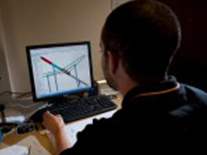
This ease with which design terminology and programming lingo has entered the lexicon allows a fast-paced exchange of ideas in a business setting, where everyone has a design engineer’s mind and understands that what they want to see is achievable on the computer. Sending files in a specified format, editing a CAD file as if it was a shopping list on Word, or distributing ideas and updates globally in a fraction of a second, the internet age has given a tech background to all walks of professional.
In the model making and prototyping industries, these tech transformations have allowed some substantial changes in how we operate; with

algorithms being used to test designs and structures for stress points before manufacture has begun, and projects being sent around the world for designing and adaptation, technology has created a better informed, better supplied, globalised marketplace.
Projects can be viewed and tweaked at the touch of a button before any manufacturing has begun. Manufacturing processes that would be impossible to replicate by hand are able to be produced by a computer in minutes and repeated time and time again without any imperfections.
For the best ways to utilise modern technology when looking to design or create a model or prototype, here are some handy points to remember.
Understand the Technology
To know the best way to manufacture an item, you need to know some of the pros and cons of different methods of production.
Design and Manufacture
SLA, or Stereolithography, is a rapid prototyping method where a model is built layer by layer using a medium that cures using ultraviolet light.
SLS stands for Selective Laser Sintering, the process of heating up a powdered substance (sometimes metal, plastic, ceramic and glass) with a laser to form solid layers in a variety of materials.
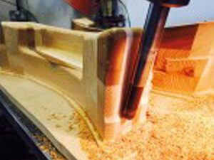
5-axis and 3-axis CNC (Computer Numerical Control) milling machines allow a multitude of drills, milling cutters, taps and other attachments to follow a computer controlled program, creating a finished design with precision. Materials that can be milled on a CNC machine include metals, model board and wood.
Laser scanning, with the combination of 3D image design, can allow reverse engineering of products to change the scale, dimensions, or simply reproduce the item in a different material. It is often much quicker (and therefore cheaper) to scan an item as opposed to drawing it from scratch in a 3D CAD program.
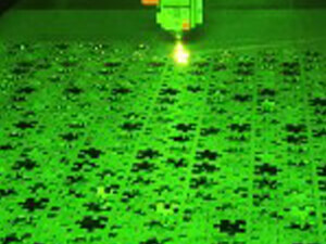
Laser cutting allows precise shapes to be cut from sheets of acrylic and other materials. While there is a limit to the shape and thickness of material, it is fast and can be used to cut repeated shapes from a sheet.
Plating a 3D printed item tends to be the process of covering the material with a thin layer of metal; this then makes the object appear to be completely metallic. This could be useful when a model or prototype manufactured from metal is too difficult or slow to machine on a CNC machining centre, so it is 3D printed and plated instead. When referring to metal items, plating tends to be for non-corrosive reasons, although it can be used aesthetically; for example, coating cheaper metals with more glamorous elements to make an object appear to be solid gold.
Fibre-glassing is the process of creating an outer casing of fibreglass, which can be a fast and effective manner of creating large corporate logos and models. Its uses range from medical casts to helicopter and yacht parts, so it is a versatile material that can be used to make all sorts of models and prototypes. It is lighter and stronger than model board, and once a mould is made, easier to mass produce.
FEA (Finite Element Analysis) is a tool used in CAD software to perform structural analysis. This is used to improve or test the structural stability of the project, as well as to test how the materials used will stand up to the challenge.
Tool Manufacture – When designing and creating a prototype or a mass-produced model, creating a tool for fibre-glassing or vacuum forming is another technique that can be performed on the CNC milling machines. This involves designing a “Master” model, either negative or positive, from which multiple replicas can be created. Depending on what the tool will be used for will depend on what material it should be made from; if the tool needs to withstand hundreds of processes, the tool is best manufactured from metal. If less replicas are needed, the tool can be manufactured from ureol (model board), which tends to make the tool cheaper to manufacture.
Inspection Tools
CMM stands for Co-ordinate Measuring Machine; accurate to 5 microns, this device is used to measure engineering components with unfaltering accuracy. When designing and creating prototypes or models, this can be used to accurately measure components to make sure everything fits together perfectly!
Faro arm is a combination of CMM technology and laser scanning, allowing us to use 3D measurement and comparisons of parts to measure items to the high standards our clients require.
Don’t Get Confused by File Types
Understanding, or having someone with the knowledge to view and convert file types is imperative in almost all areas of technology. With so many

different programs for designing projects and graphics, you want to make sure the person you are sending the information can view it; conversion tools can be utilised, but most programs allow you to save files in more formats than you’d ever need. Here are some of the more common file formats utilised in designing and 3D printing.
IGES – Initial Graphics Exchange Specification. Standardised file format for moving 3D model files between CAD software. Older file format, now mostly superseded by STEP.
STEP File – Standard for the Exchange of Product information file. A format for viewing and exchanging data between CAD and CAM systems.
STL – Stereolithagraphy file format. Specifically for 3D printing, this file type shows shape information without colour or texture.
SLDPRT – Solidworks file. This is the program our designers tend to use, and is one of the industry standards is the engineering and design world.
PDF – Perfect for general viewing of 2D and 3D designs. Hard to edit, easy to annotate. This file type can be used for consultation
DXF – 2D and 3D format, which can be opened in AutoCad as well as other programs.
Hopefully this breakdown of file types and processes will help you with your product’s transformation from concept to prototype, or from design to model. With the constantly updating world of tech, and the constant investment in technology here at JH May, there will always be some technical jargon that needs clarifying for clients. If any more information on any of these subjects is required, contact us for a consultation on the manufacturing process and we can explain it to you in easy to understand terms.